

The Open Systems Interconnection (OSI) Model is a standard used by networking manufacturers globally. It was created and published in 1984; it splits all network communications into seven layers. Each layer serves the layer that’s above it plus the layer beneath it which adds additional capabilities.
Data between two devices travels down the stack on the device’s A-side (wrapped at each layer) and gets transmitted before moving up the stack at the devices B-side (where the wrapping gets stripped away at every stage). This data wrapping process is called encapsulation.
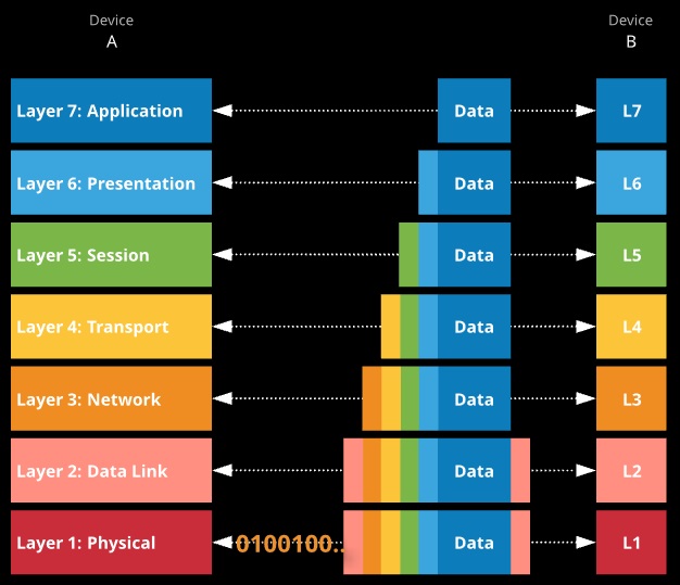
At Layer 1 (Physical), networks use a shared medium where devices can transmit signals and listen.
Layer 1 showcases how data gets received and transmitted while taking into consideration the medium, voltages, and RF details.
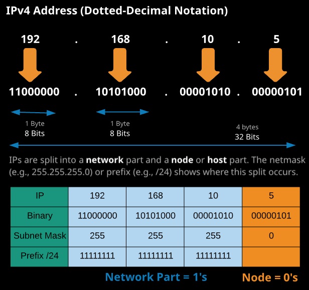
IPv4 addresses are how two devices can communicate at layer 4 and above of the 051 seven-layer model. IP addresses (IPs) are actually 32-bit binary values but are represented in dotted-decimal notation to make them easier for humans to read and understand.
Subnetting is a process of breaking a network down into smaller subnetworks. You might be allocated a public range for your business or decide on a private range for a VPC. Subnetting allows you to break it into smaller allocations for use in smaller networks (e.g., VPC subnets).
If you pick 10.0.0.0/16 for your VPC, it’s a single network from 10.0.0.0 to 10.0.255.255 and offers 65,536 addresses. That VPC could have a single subnet within it that’s also 10.0.0.0/16.
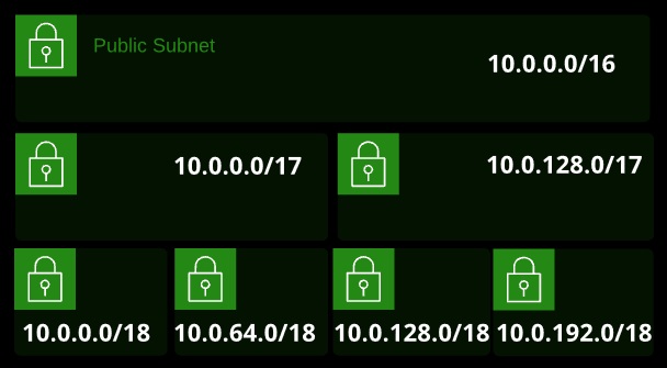
With a certain size of VPC, increasing the prefix creates two smaller networks. Increasing again creates four even smaller networks. Increasing again creates eight even smaller — and so on.
You won’t need to know this from memory — there are plenty of cheat sheets available to help you along the way.
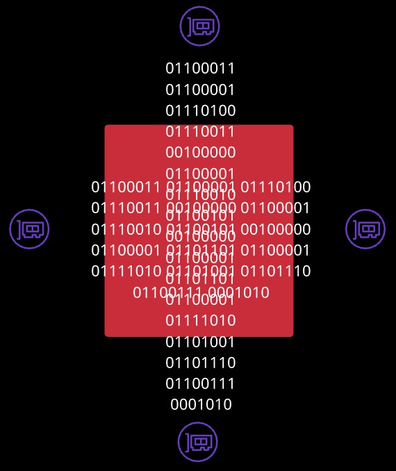
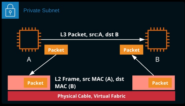
Local device-to-device communication takes place using Ll (Physical) and L2 (Data Link) using MAC addresses and physical 0’s and I ‘s. This doesn’t scale across LANs, so a method of network-to-network transit is needed. IP routing provides this. The method used depends on if the two devices are local, in a known remote network, or in an unknown network.
IP-to-IP communication that occurs locally doesn’t use a router. ARP is used to find the MAC address for the destination IP address. The IP packet is created at L3 and passed to L2, where it’s encapsulated inside an ethernet (L2) frame. The frame is sent to the destination MAC address. Once received, the L2 frame is removed and the IP packet is passed to L3.
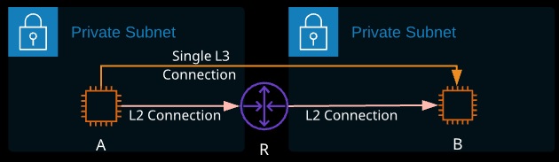
If Instance A wants to communicate with Instance B, it can use its IP and subnet mask to determine if B is local. If it’s not, then the following process occurs:
- “A” generates an L3 packet — the SRC is the IP-“A”, the DST is IP-“B”
- “A” knows its default gateway (Router) IP, so it uses ARP to find the Router MAC
- “A” passes the L3 packet to L2, wraps it in an L2 frame, and sends this to the R-MAC address (not the MAC address of B)
- “R” receives this, strips away the Layer 2 frame, and checks the DST IP
- It knows the network of IP-“B” because it’s connected to it
- “R” uses ARP to find the MAC of “B,” generates a frame TO “B”, puts the unaltered IP packet inside, and sends to MAC-“B”
- “B” receives the frame, strips it way and passes the packet to L3
Routing works equally well whether the network of the remote instance is known or not. In this case, Instance A is attempting to communicate with Instance C.
Instance A knows Instance C is not local, so it creates an IP packet with a dst of Instance C. It passes the packet down to L2 and asks for it to be addressed to the MAC address of Router A (its default router/route).
Router A strips the L2 frame and reviews the destination address of the L3 packet. It doesn’t know Network 3, so it has no knowledge of how to get there. It does have a “default router,” which is Router B. It creates an L2 frame with a dst MAC of Router B and wraps it around the unchanged packet.
The internet uses a routing protocol called Border Gateway Protocol (BGP). This protocol exchanges routes. Router C would advertise Network 3, and Router B would learn about Network 3 via Router C. Router B would advertise Network 3 via Router C. Router A would learn all Router B’s routes and all routes it knows about.
Router C receives the L2 frame, strips it away, and reviews the L3 packet. It now knows it’s in the same network, and it finds the MAC address of the DST IP address of C. A new L2 frame is created, with a dst MAC address of C, and it forwards it in.
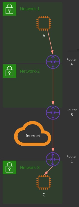
At scale, this is how the Internet works: Unchanged packets being passed around from router to router, each time using a new L2 connection.
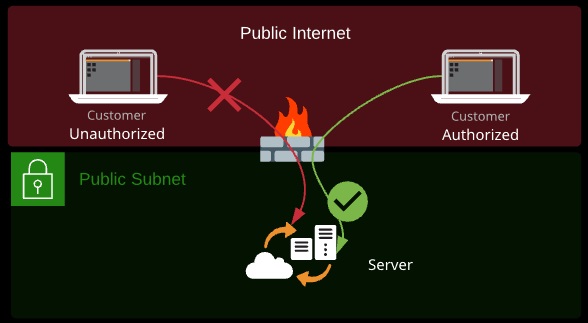
A firewall is a device that historically sits at the border between different networks and monitors traffic flowing between them. A firewall is capable of reading packet data and either allowing or denying traffic based on that data.
Firewalls establish a barrier between networks of different security levels and historically have been the first line of defense against perimeter attacks.
What data a firewall can read and act on depends on the OSI layer the firewall operates at:
- Layer 3 (Network): Source/destination IP addresses or ranges
- Layer 4 (Transport): Protocol (TCP/UDP) and port numbers
- Layer 5 (Session): As layer 4, but understand response traffic
- Layer 7 (Application): Application specifics (e.g., HTML paths, images)
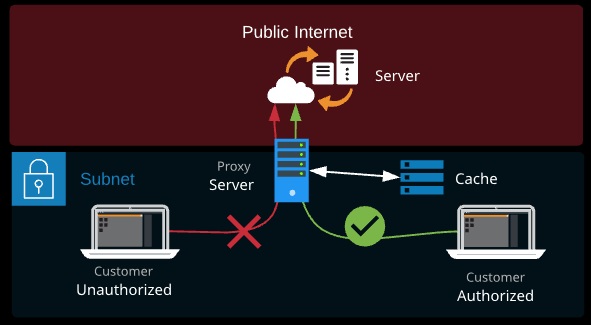
A proxy server is a type of gateway that sits between a private and public network (e.g., the Internet). A proxy server is something that generally needs application support and is configured in the operating system, a web browser, or another application.
The client makes a connection to the proxy server, and the proxy makes a connection to the destination server. Proxy servers can provide filtering (child safety, malware, removing adult content) or it can act as a web cache, speeding up web access for a large organization at a remote site.
Proxy servers can also choose to pass on traffic or not based on things network layer appliances can’t, like username or elements of a corporate identity — department, age, security privilege, or the DNS name rather than IP.
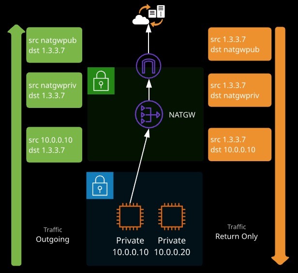
Network address translation (NAT) is a method of remapping source IPs or destination IPs of packets. It can be used in a number of ways.
- Static NAT: A private IP is mapped to a public IP (what IGWs do)
- Dynamic NAT: A range of private addresses are mapped onto one or more public (used by your home router and NAT gateways)